Ultimate front spider.

Curious

New member
I plan to make a front spider sometime soon and have been mulling over a couple of options but would like to know your thoughts guys on what your currently using or if you were to make a new one how you would spec it to possibley improve on the one you currently have?

Things Im thinking about are;

The number and size of the contact points - would 6 be better than 4 or would 8 be king - with 8 I could adjust with 4 and then snug things a little tighter later?

The profile of the contact points - are flats ok depending on screw contact point diameter or should the points be domed?

The pitch of the screws - how fine do we really need to go to make adjustment nice and progressive without jumping past?

Screw diameter?

Any other thoughts on the ultimate front spider design?

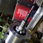
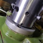
Now Ive been working just fine in a 4 jaw with round contact pads added but I had a 20" barrel this week that made things a little more tricky in that I had to fit an extension to the muzzle end so I could still reach my back spider. If I dropped the 4 jaw I would gain another 4 inches hence making a front spider will be wise.

With the collective knowledge we have here could we design the ultimate front spider I wonder?
 
Last edited:
Just from a machinist standpoint, I would think a 4 screw spider would be just right, untilizing 1/2 20tpi screws.

With 4 screws, you have two always opposing each other, giving adequate clamping ability combined with the ease of truing.

I suppose you could employ more, but the benefits might prove neglible.
 
Anything more than 4 screws will just eat up time dialing in the barrel. I use 1/2-20 set screws with brass inserts, flat. In a perfect world the screws would have feet that pivoted on a ball but that adds too much length to the screws. I've made several spiders out of backing plates for chucks but that leaves the screws exposed and sooner or later they will bite you. My fingers have sounded like a playing card in bicycle spokes. One time my arm was doing 1250 RPMs and I tore the sleeves out of a sweater and long sleeve shirt getting away from the damn thing. Just stupidity on my part. Make a full diameter spider where you can have the set screws at or below the surface of the OD. You may end up with two sets of screws, different lengths.
 
I use 1/2x20 also, but use copper tips made from copper ground rod bought at Home Depot. I needed a shorter distance as my headstock is wide. I machine a faceplate about a 1/2" thinner and installed a 5/8" thick aluminum plate to it and drilled and tapped it in the mill in my indexing head. I found short 5/8"x20tpi set screws at McMaster Carr.
 
Anything more than 4 screws will just eat up time dialing in the barrel. I use 1/2-20 set screws with brass inserts, flat. In a perfect world the screws would have feet that pivoted on a ball but that adds too much length to the screws. I've made several spiders out of backing plates for chucks but that leaves the screws exposed and sooner or later they will bite you. My fingers have sounded like a playing card in bicycle spokes. One time my arm was doing 1250 RPMs and I tore the sleeves out of a sweater and long sleeve shirt getting away from the damn thing. Just stupidity on my part. Make a full diameter spider where you can have the set screws at or below the surface of the OD. You may end up with two sets of screws, different lengths.

Dave,

Check the link. I think the ones at the top could be made to work without being too long. Nothing in 1/2-20, though.

Justin
 
Since I am newbie, I see no limit on my quest for continuous improvements, failure IS an option. The last one I conceived is this one. I don't have 1/2 x 20 tap and bolts so I used what I have. 3/8 x 24. The spider screws are set screws with cup points to mate with ball bearings on the aluminium finger clamps. Then I have a set of 8 socket heads with brass tips to provide the additional insurance to ensure the workholding integrity.

I still dial in the front and back spiders the same way, once dialed in I slowly tighten the clampdown sockets monitoring the dial indicators to make sure they dont move. Using 2 wrenches doing the opposite screws seems to maintain the dialed in integrity.

I am open for criticism, do you folks see any drawbacks on this set up?
 

Attachments

  • 20161214_174702.jpg
    20161214_174702.jpg
    1.6 MB · Views: 860
  • 20161214_174647.jpg
    20161214_174647.jpg
    1.5 MB · Views: 705
Last edited:
Since I am newbie, I see no limit on my quest for continuous improvements, failure IS an option. The last one I conceived is this one. I don't have 1/2 x 20 tap and bolts so I used what I have. 3/8 x 24. The spider screws are set screws with cup points to mate with ball bearings on the aluminium finger clamps. Then I have a set of 8 socket heads with brass tips to provide the additional insurance to ensure the workholding integrity.

I still dial in the front and back spiders the same way, once dialed in I slowly tighten the clampdown sockets monitoring the dial indicators to make sure they dont move. Using 2 wrenches doing the opposite screws seems to maintain the dialed in integrity.

I am open for criticism, do you folks see any drawbacks on this set up?

I guess my first impression,... you have a lot of unsupported distance from headstock to where the barrel is being machined. Second, why not use a four jaw chuck? What are the advantages to your method? Not a criticism just a question.

Jerry Halcomb
 
nez,
only the length.
most , not all are trying to mount short bbls in long
head socks, so the shorter the tool the better.
taps are cheap.
with multiple holding points, you may induce stress/bending,
not really two point mounting.
i'm just a beginner too.

Since I am newbie, I see no limit on my quest for continuous improvements, failure IS an option. The last one I conceived is this one. I don't have 1/2 x 20 tap and bolts so I used what I have. 3/8 x 24. The spider screws are set screws with cup points to mate with ball bearings on the aluminium finger clamps. Then I have a set of 8 socket heads with brass tips to provide the additional insurance to ensure the workholding integrity.

I still dial in the front and back spiders the same way, once dialed in I slowly tighten the clampdown sockets monitoring the dial indicators to make sure they dont move. Using 2 wrenches doing the opposite screws seems to maintain the dialed in integrity.

I am open for criticism, do you folks see any drawbacks on this set up?
 
Gents,

I think the length is a necessity for Nez as it looks to me, based on what I am seeing on his spider, like he is chambering using the Gordy method. Nez...am I correct? And how is your chuck attached to the lathe?

I like your ball bearing and finger clamp arrangement. I've thought of doing something similar but have never got around to it.

Justin
 
I know a little and will guess the rest. I know his spider is threaded to the spindle. His hole through the spindle is too small or he would have built a conventional short spider on the RH side and shortened it up. It is a 10x24 lathe with a max of 1" spindle bore. I don't believe a 4 jaw is a good way to do it.
Nez didn't chamber the winning SR barrels at Camp Perry this year doing sub standard work. His shooters were #1 and #3 in the Presidents 100 and set a new National team record. Beat the old team record by a bunch. If you know anything about Service Rifles and Camp Perry, you will appreciate their success.
 
yes i saw the ar bbl.
i am glad nez got a lathe and it fits his needs.
( a 1" bore is fine when doing most ar15 type bbls)
 
Gents,

I think the length is a necessity for Nez as it looks to me, based on what I am seeing on his spider, like he is chambering using the Gordy method. Nez...am I correct? And how is your chuck attached to the lathe?

I like your ball bearing and finger clamp arrangement. I've thought of doing something similar but have never got around to it.

Justin

The lathe is a 1024 with a threaded nose, the chuck is threaded straight to the spindle. I could have made the chuck a little shorter, the problem with this lathe, the coupler to the lead screw is unusually long that apron bottoms out on the coupler if I were to cut the 4 inch chuck shorter than 3 inches. I suppose I can make it 3 inches long

In the picture you may see the coupler sticking out.
 

Attachments

  • 20161214_174745.jpg
    20161214_174745.jpg
    1.8 MB · Views: 689
yes i saw the ar bbl.
i am glad nez got a lathe and it fits his needs.
( a 1" bore is fine when doing most ar15 type bbls)

I can accommodate barrels that come in at 1.032 and 24 inches long, just enough length sticking out after I cut an inch off the chamber side.
 
nez,
only the length.
most , not all are trying to mount short bbls in long
head socks, so the shorter the tool the better.
taps are cheap.
with multiple holding points, you may induce stress/bending,
not really two point mounting.
i'm just a beginner too.

Thank you for the input on the bending aspect.

When I tried tightening the clamp down sockets one by by one I can see the DI moves, so I tried the 2 wrench approach on the opposing sockets while keeping the needle stationary. Still trying different ways. I may still lop off the spiders screw holes and drill/tap new ones for 1/2 x20, asking the spider even shorter and not use the socket head clamps.
 
yes i saw the ar bbl.
i am glad nez got a lathe and it fits his needs.
( a 1" bore is fine when doing most ar15 type bbls)

Nez will always be nice to you! He does have a couple lathes, a lot of good tooling, and an engineer's knowledge.
Don't sell him short!
 
The lathe is a 1024 with a threaded nose, the chuck is threaded straight to the spindle. I could have made the chuck a little shorter, the problem with this lathe, the coupler to the lead screw is unusually long that apron bottoms out on the coupler if I were to cut the 4 inch chuck shorter than 3 inches. I suppose I can make it 3 inches long

In the picture you may see the coupler sticking out.

Nez,

Ahhhh...I get it now. I thought you were dealing with a long headstock, and the spider with fore and aft adjustment was your work around it.

I'd be surprised if there was much flex in that spider when chambering. I built something similar to true actions in and it is hell-for-stout. See thread below.

http://benchrest.com/showthread.php?91625-Action-Truing-Justin-Style&highlight=

Based on what Butch said, that spider seems to be working just fine! Nice work.

Justin
 
I use socket head cap screws for all of mine, 7/16-20 or 1/2-20 I do this for two reasons, #1, safety and #2 because I can get a part really well dialed in with my fingers....really well dialed in. The large knurled head (actually splined or siped) allows for good finger manipilation.


I have several with screws that stick out as Tooley described eating hisself....I keep rolls of tape hanging over my lathe. Black tape, duct tape and car masking tape (automotive grade, from the painting supplier...this IS NOT like hardware store tape) which I wrap around the exposed screws like a wheel on spokes which makes it less dangerous than a bicycle wheel.

Haven't been able to get brass ground rods around here for 20yrs....i WISH!...I order brass stock from the interweb or buy it at Metal Supermarkets.

I make 'L' shaped shims of AL and copper/brass as well as keeping a dish of 1/2"X1/8"X3" splinters at hand in a bowl.
 
Groung rods are copper

Ground rods are made of copper or most 5/8" have a thin copper outer skin and a steel core. Some of the ground rods made these days look to have a electroplating of copper, very thin.


Hal
 
Ground rods are made of copper or most 5/8" have a thin copper outer skin and a steel core. Some of the ground rods made these days look to have a electroplating of copper, very thin.


Hal

All ground rods here In The Left have been electroplated steel for lo these 20yrs....brass/copper/bronze stock NA
 
Back
Top