Hey Dusty, put this on that Big 300 Merc

jackie schmidt

New member

Attachments

  • image.jpg
    image.jpg
    30.3 KB · Views: 945
  • image.jpg
    image.jpg
    32.3 KB · Views: 847
  • image.jpg
    image.jpg
    33.4 KB · Views: 799
  • image.jpg
    image.jpg
    33.8 KB · Views: 781
Last edited:
The wheel fits A big single screw Harbor Tug. It's a shade under 12 ft in diameter, is turned by a 4000 HP EMD Diesel.

The ripples just appear that way. The Wheel Shops polish the blades with big rotary sanders that leave that finish. You really can't feel them.

The blad s are squared off on the tips because it runs inside a big Kort Nozzle.

G&H Towing is who owns it. The have the contract for handling ships in the Houston/Galveston ship channels. We do all of their propellor shaft and rudder work.
 
Last edited:
Hey i got a large collection of handmade wheels- i even have a miniature version that looks just like that i had on a mastercraft. That would look cool on there tho.
 
Jackie
I really like those shop photos. It reminded me of some of the stuff I got to work on. The shop I worked in was run by the Navy so some of the things that came in were pretty big. Railroad tracts came into one end of the building and they would bring the big stuff in on a flatcar. The two largest pieces that came in while I worked there was a rudder and the rudder shaft or prop shaft. Whatever the shaft was it was a large. Anyway, they were off the aircraft carrier Midway. The rudder was setup in front of the biggest floor mill we had in the shop. The day shift did all the work and all I had to do was make some chips. The tool and die shop made a simple but really neat fixture for cutting the taper. Each pass took awhile and I could peek into the top drawer of my roll around and check out Guns And Ammo or Hot Rod magazine.
Sometimes you get the gravy and sometimes you have to do the setup. the shaft came in on in the swing shift and it was my job to put it in the longest lathe in the shop. I ran around with a rag tape making chalk marks just off the ways so the riggers could lift and position the steady rests and so it went. When you have one or two riggers and the crane operator waiting on you to move the job along you have to get with the program.
The Navy was big on recording jobs with photos for future reference, and if you worked the job you could have copies. I have tried to post them but the clarity is really bad. They are 8 by 10 and really clear so I'm doing something wrong. Will try again later.

Here is a picture of that 13 inch shaft in our big LeBlond NR getting ready to prep it for rebuild, This is one of our older machines, but it is a fine old machine.

A number of years ago, we won the bid to machine eight 24 inch diameter 18 ft long Shafts for four 25,000 HP Seagoing Notch Tugs. The shafts had a 36" diameter flange forged on. The raw forging weighed around 26,000 lbs. That old NR did a great job on them.

The 1st picture is a 9 inch shaft in our 32 ft Lehmann Lathe. That Shafts of this size are our bread and butter.


http://benchrest.com/attachment.php?attachmentid=17545&stc=1&d=1457491034

http://benchrest.com/attachment.php?attachmentid=17546&stc=1&d=1457491170
 

Attachments

  • image.jpg
    image.jpg
    38.7 KB · Views: 545
  • image.jpg
    image.jpg
    35.7 KB · Views: 522
Last edited:
Ive seen some big machines being around turbine generators for power plants. I seen one lathe that had a seat on it to ride. It took into account the sag of the shaft as it went along and pulled off blue chips as big as my arm. Ive also seen a mill lathe type machine that turned the floor mounted chuck and the shaft ran down into the basement and up towatd the roof. Ive also seen drill bits that drill square, triangle or hex holes. I love seeing the out of the ordinary stuff.
 
I once had a catalog of the 1932 British machine exposition that had a couple of engravings of those lathes, Dusty. Also an interesting lathe that trued both wheels of a steam engine at the same time on the axle. Some of the designs didn't seem to offer much concern for the well being of the operators.
 
Jackie,Thanks for the photos. Love this stuff. Is that two carriages on the LeBlond? What does NR stand for?
 
Jackie,Thanks for the photos. Love this stuff. Is that two carriages on the LeBlond? What does NR stand for?

Yes. Dual carriages are almost a nessessity in our line of work. Our 32 ft Lehman and our 28 ft Lebland also have duel carriages.

Our new 28 ft Kingston is only single, but we make do. I enclosed a picture.

http://benchrest.com/attachment.php?attachmentid=17547&stc=1&d=1457568283

As for NR, I really don't know what it stands for. Those big lathes were made from the beginning of WW-2 through the '60's. Our's came out of government storage, it was built in the mid '50's.

One problem we had with it after several years of service was the Head Bearing. Our top machinist, who ran it quite a bit, started complaining that he could not get any true spots for steady rest, and the lathe was leaving a district "pattern" on long shafts.

The problem was the main splindle head bearing. It had developed track marks on the race and the chuck side rollers. We called LeBland, and they had the bearing assembly.

$28,000 dollars. But that included there mechanic flying down to install it. Not a bad deal, really.

Since then, no trouble.

We did convert it to a frequency drive for starting and stopping. The original resistor bank/dash pot system was just worn out, and parts were non existent. We had a local Electric Motor Shop design a Frequency Control to stop and start the 75 HP motor. It sounds like a jet irliner taking off when you hit the start button.
 

Attachments

  • image.jpg
    image.jpg
    41.8 KB · Views: 432
Last edited:
The Rudder

boring bar.jpg
rudder1.jpg
rudder2.jpg

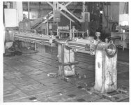
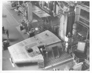
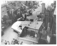
Photo #1 is the fixture for boring tapers that the tool and die shop made. It's simple but really neat. A lot of craftsmanship here. Check out the hand welds on the two base pieces. Photos #2 & #3 show the Morton floor mill. These photos were taken from the lift that was used to transfer material to be machined anywhere in the shop. The lathe I put the rudder shaft in isn't shown but is to the right of the planer table.
 
View attachment 17608
View attachment 17609
View attachment 17610

Photo #1 is the fixture for boring tapers that the tool and die shop made. It's simple but really neat. A lot of craftsmanship here. Check out the hand welds on the two base pieces. Photos #2 & #3 show the Morton floor mill. These photos were taken from the lift that was used to transfer material to be machined anywhere in the shop. The lathe I put the rudder shaft in isn't shown but is to the right of the planer table.

We have performed that exact same operation on large rudders. The main difference being we built portable boring bars that cut 1 inch taper to the foot to bore a 48 inch long tapers in large cast steel rudder frames that weighed about 25,000 lbs. The contractor, (Halter Marine in Mobile Alabama), fabricated the blades onto the frames after all the machine work was performed. The frames also had a 16" diameter Pintol Pin Fit in the lower section that had to be bored in line with the top taper.

A big challenge in this was cutting the 3" wide key way after boring. We bought a huge Shaper that had a 60" stroke. It was manufactured by The Ohio Machine Co back in WW-2 and had "Dreadnought" cast on the ram. We sold it a few years ago, because after we did those 6 huge rudder frames, we never used it again.

I am putting together a bid package right now for boring, in place, the abutment supports and boom heel pin fits for a huge Dredge Boat Boom. The holes are 24" diameter, approx 12" long. We have to bore them round and truly straight to accept new non metallic Thordon Bearings.
 
Here is a video you might enjoy of me align boring the Struts and Stern Tube Bearing Fits on a new 2500 HP Push Boat.

We do a lot of this type of work, both on new vessels and repair.

We built just about everything you see here, they are compact, brutally powerful, and I can bore round and truly straight holes. You can see by the shavings how much metal I can remove on each pass.

The small bar is 3 3/4 inches diameter by 6 ft long, the larger bar is 4 1/2 diameter 14 ft long. Both are hard chrome plated and run in cast iron bearings.

On a job like this, we leave about 1/2 inch of stock in the rough Tubes, and the Shipyard fabricates it all together as close as they can. We then establish proof marks on the tubes, working with either a Lazer or Music Wire. These proof marks, (look close at the small punch marks inside those white circles on the Tubes), are what I use to align the Bars.

These particular holes are 11.000 finished inside diameter.

I know this looks rather crude in today's CAD/CAM/CNC World, but this is a big money maker for us. The Boring Bars are air powered by the big pneumatic motors you see in the video.

The accompanying pictures are a finished bored hole and that hull as the shipyard prepares to launch it onto a dry dock.
http://benchrest.com/attachment.php?attachmentid=17627&stc=1&d=1459478672

http://benchrest.com/attachment.php?attachmentid=17626&stc=1&d=1459478114


https://www.youtube.com/watch?v=NgFpC6jBdJU
 

Attachments

  • image.jpg
    image.jpg
    29.9 KB · Views: 309
  • image.jpg
    image.jpg
    26.2 KB · Views: 295
Last edited:
Jackie, you were reading my mind. When you said portable boring bar I was trying to picture that and how it is powered. I was thinking air only because we had a couple of portable machines that were used aboard ship and they were air powered. If the ship yard had a portable boring bar somewhere I never saw it.
Anyway, I enjoyed the video and I am not done watching it. The setup took more than a little thought.
How was music wire used to establish proof marks?
You mentioned LeBlond in a previous post. The yard bought one to replace one of the old Axel lathes. Some of the levers were replaced by one or two dials on the head stock. You could hear it change gears.
I been away from the trade for 45 years but have never lost interest
 
Jackie youre an animal. Doin stuff most would think impossible. Ive seen some setups kinda like that to bore turbine bearing raceways. They just used a little hydraulic motor and couldnt take much at a pass.
Btw- i thought tug boats had some kind of helicopter blade type setup that allowed them to go any direction at any time? Is that something different?

Dusty, the term "tug boat" is used to describe a vessel that is used to assist ships in their manueavering in harbors and channels. The term "push boat" generally means a vessel that pushes barges full of cargo.

Yes, many "tugs" have drive systems that are not propellars, but verticle blades that articulate as hey rotate and an infinite angle to allow the tug to be highly maneuverable.

https://www.youtube.com/watch?v=rsk-3l9yslc

Push Boats generally have standard twin propellers, main steering rudders behind the propellers, and flanking rudders forward of the propellers.
 
Back
Top