Using what you have on hand.

jackie schmidt

New member
I have decided to convert my Rail Gun Barrel Block to front a V to a round non metallic sleeve.

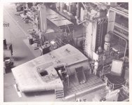
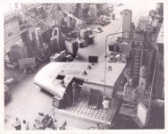
I could do it several ways, but decided to do it on our big Lucas Horizontal Boring mill.

I thought you all would get a laugh out of an obvious exercise in overkill:D

But you use what’s handy for the job on hand.

http://benchrest.com/attachment.php?attachmentid=23127&stc=1&d=1574433215
 

Attachments

  • 7B2E33EE-B764-4E92-8C70-E9F5D09276D3.jpeg
    7B2E33EE-B764-4E92-8C70-E9F5D09276D3.jpeg
    3.6 MB · Views: 1,036
What material are you going to use for the sleeve? I have asked several people about this and they all seem to have different ideas on it. I was going to try one out last year but didn't get around to it. I also didn't want to disturb my rail since it had the best barrel I have ever owned on it.

Joe Hynes
 
Nothing wrong with that Jackie. How much horsepower does that mill have? I know a lot of those old Lucas horizontals were 15hp+.

I almost did a V block on my rail but went the delrin sleeve route instead. V's are nice for running different barrel diameters, but I chose to make a few sleeves (1.25, 1.35, and 1.45)

-Lee
www.singleactions.com
 
What material are you going to use for the sleeve? I have asked several people about this and they all seem to have different ideas on it. I was going to try one out last year but didn't get around to it. I also didn't want to disturb my rail since it had the best barrel I have ever owned on it.

Joe Hynes

I am going to try a woven material called Marine Blue. We use it a lot fo non metic bushings.

I have on hand Delren, CIP, ( another woven material), Thorplas, UHMJ, Nylon and Micarta. I thought I would try this.

http://benchrest.com/attachment.php?attachmentid=23130&stc=1&d=1574456479
 

Attachments

  • image.jpg
    image.jpg
    2.4 MB · Views: 745
Last edited:
0014.jpg0015.jpg


Jackie,
Great pic that brought back memories of the shipyard. If you did it on this floor mill ,and I BET YOU COULD...that would be some serious overkill !

Mort
 
Last edited:
View attachment 23128View attachment 23129


Jackie,
Great pic that brought back memories of the shipyard. If you did it on this floor mill ,and I BET YOU COULD...that would be some serious overkill !

Mort

That's so cool..... I didn't even know "floor mills" existed until this pic. In retrospect it's an obvious solution for large work and once I'd thought about it I searched the innertube and sure enough, there's one not 5 miles down the road from me. And many more between here and the coast.....

So much I don't know that I don't know what I don't know

thank you
 
View attachment 23128View attachment 23129


Jackie,
Great pic that brought back memories of the shipyard. If you did it on this floor mill ,and I BET YOU COULD...that would be some serious overkill !

Mort

Nice picture.

That is a large rudder that they are machining. I have actually repaired a rudder that large, (it weight 35,000 pounds), but we did it with portable boring bars.

The pintal pin had come loose and had wallowed out the fit. ( that is located in the boss just forward of the square access hole in your picture. We rebored it in alignment with the upper stock fit. We repaired the pin by welding it up with submerged arc stainless and remachining it.
 
Last edited:
The rudder

That rudder is from the aircraft carrier Midway. Rudders coming into the shop had the bore built up with weld. How they did that I don't really know. I don't think we used carbide because of the interrupted cuts getting through the weld.

The boring bar and fixtures were made inhouse used a simple star feed for both the upper and lower segments.

Large work like the rudder would role into the shop on small railroad flatcars. The overhead crane and a rigger would move the work to the proper machine.

I never did a rudder setup which is time-consuming and took two machinists. Once you start cutting it's a one man show. That's where I came in on the night shift.

The taper was built into the boring bar. If I find a pic I will post it.

Mort
 
Last edited:
Mort, I have build boring bars that cut the taper in those large rudder frames.

Back in the ‘80’s we had a contract with Halter Marine in Mobile to do the machine shop work on five 20,000 HP sea going tugs. The rudders were built on a frame that had a 40 inch long taper fit at the top, the top was 14 inches diameter and tapered at 1 inch to the foot. It had a 3 inch wide key way.

That contract is the reason we bought that big LeBlond Lathe we are now getting rid of. The main prop shafts were 20 inch diameter, about 18 feet long, with a 36 inch diameter flange forged on one end.

I learned a lot doing that job. We even built a small taper cutting boring bar to do the tapered coupling bolt’s. They were a nominal 3 inch diameter on the big end.

It’s hard to believe that was over 30 years ago.
 
That's so cool..... I didn't even know "floor mills" existed until this pic. In retrospect it's an obvious solution for large work and once I'd thought about it I searched the innertube and sure enough, there's one not 5 miles down the road from me. And many more between here and the coast.....

So much I don't know that I don't know what I don't know

thank you

Al, the machine Jackie is using is called a Horizontal Boring Mill HBM. They are common in big shops and come in several configurations. They are made by Lucas, Cincinnati-Gilbert, Bullard, Giddingx&Lewiss and a few others.

The last one I was a Project Engineer on was a Giddings&Lewis Floor Type. It took 128 cubic yards of reinforced concrete for its foundation and could take an 85 hp cut 12’ above the floor. It was CNC. Had 12’ xaxis, 12’ yaxis, 6’ zaxis, and 5’ waxis.

This was in 1995 and the US had become spooked by the environmentalists we had to get the castings poured in Japan.

.
 
Last edited:
Mort, I have build boring bars that cut the taper in those large rudder frames.

Back in the ‘80’s we had a contract with Halter Marine in Mobile to do the machine shop work on five 20,000 HP sea going tugs. The rudders were built on a frame that had a 40 inch long taper fit at the top, the top was 14 inches diameter and tapered at 1 inch to the foot. It had a 3 inch wide key way.

That contract is the reason we bought that big LeBlond Lathe we are now getting rid of. The main prop shafts were 20 inch diameter, about 18 feet long, with a 36 inch diameter flange forged on one end.

I learned a lot doing that job. We even built a small taper cutting boring bar to do the tapered coupling bolt’s. They were a nominal 3 inch diameter on the big end.

It’s hard to believe that was over 30 years ago.

Jackie,

I'm not following you on the boring bar that cuts a taper, I'm assuming, without using the compound. Is this boring bar a form tool of sorts?

Justin
 
Jackie,

I'm not following you on the boring bar that cuts a taper, I'm assuming, without using the compound. Is this boring bar a form tool of sorts?

Justin

This is a simple sketch portable bar to bore a large diameter taper in a large frame.


http://benchrest.com/attachment.php?attachmentid=23139&stc=1&d=1574720443

The tool block channel is milled parallel with the taper. The fitted tool block travels down the channel, advanced by the screw. The star feed hits a bar every revolution.

Simple, but effective.
 

Attachments

  • A0E0E3BB-078B-44F4-869A-BAE12C067FA3.jpeg
    A0E0E3BB-078B-44F4-869A-BAE12C067FA3.jpeg
    2.9 MB · Views: 548
Last edited:
Rudders

Nice illustration Jackie.

I'm curious about your choice of tooling....Carbide or HSS?

Mort
 
Nice illustration Jackie.

I'm curious about your choice of tooling....Carbide or HSS?

Mort

The only tools we use HSS in are our portable boring bars. These bars work on a slower rpm with more feed, typically .008 inch per revolution.

I’m not sure if I have ever posted this video, but here are two of our boring bars set up in and align boring the Strut and Stern Tube of a new boat.


https://www.youtube.com/watch?v=NgFpC6jBdJU
 
Last edited:
The only tools we use HSS in are our portable boring bars. These bars work on a slower rpm with more feed, typically .008 inch per revolution.

I’m not sure if I have ever posted this video, but here are two of our boring bars set up in and align boring the Strut and Stern Tube of a new boat.


https://www.youtube.com/watch?v=NgFpC6jBdJU


Fan tastic


Not only can you sketch a concept but you can document work in a way that allows a layman to comprehend.

You are a great teacher, bravo

and Thank You
 
The way we do these, we leave 1/2 inch of stock in the tubes for final boring. The Shipyard can certainly fabricatethe tubes in that close. I generally take a rough cut of 3/16 to the side, then a light straightening cut, then finish you want to leave about 1/32 for the finish cut.

It is no problem taking 1/4 to the side cuts with these bars, depending on the bearing spread. Power is not an issue. The big air motors are 5 HP units at 3000 rpm into a 50 to 1 gear reduction. This drives the gear assembly on the bar which is 8 to 1 reduction.
 
Last edited:
Back
Top